
 English
 عربى
 русский
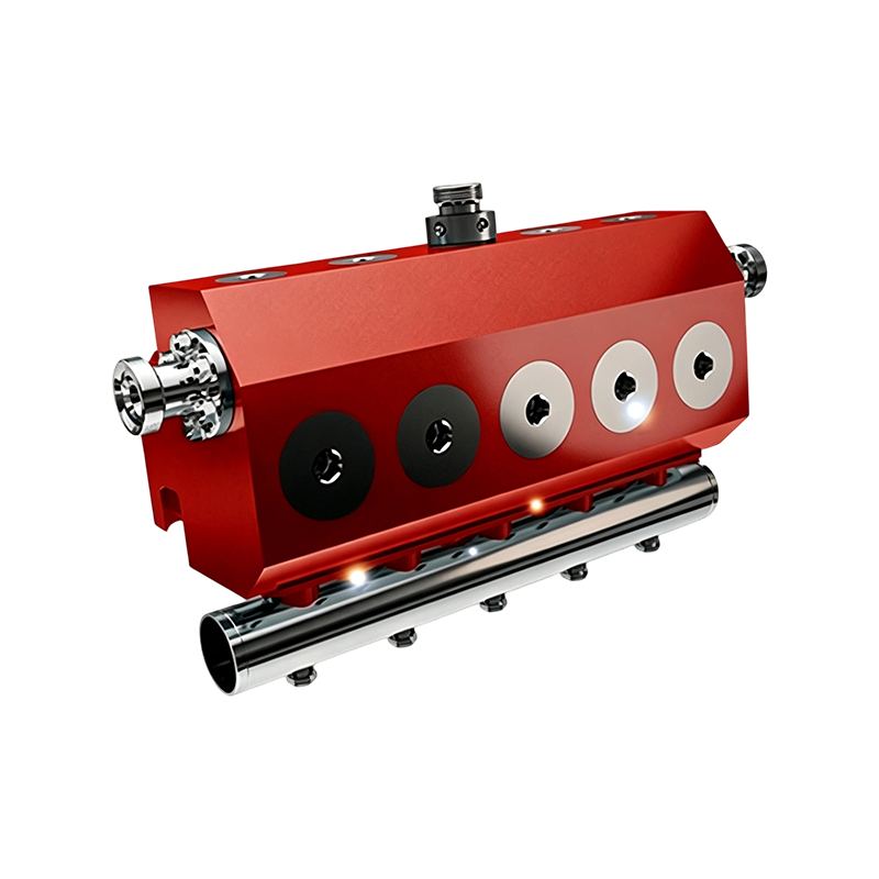
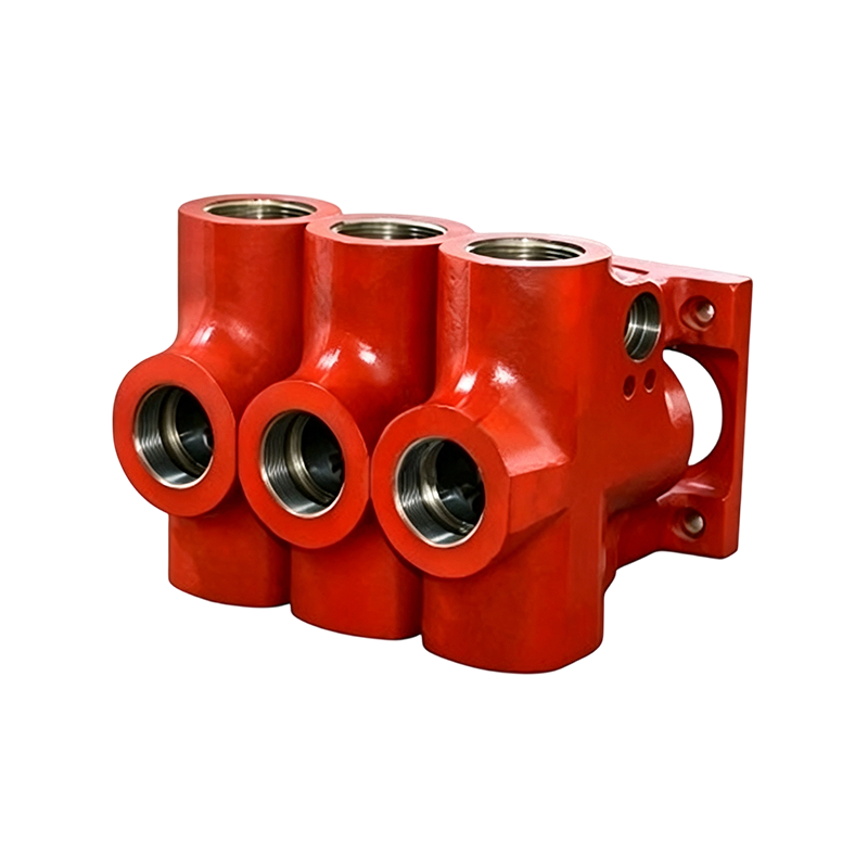
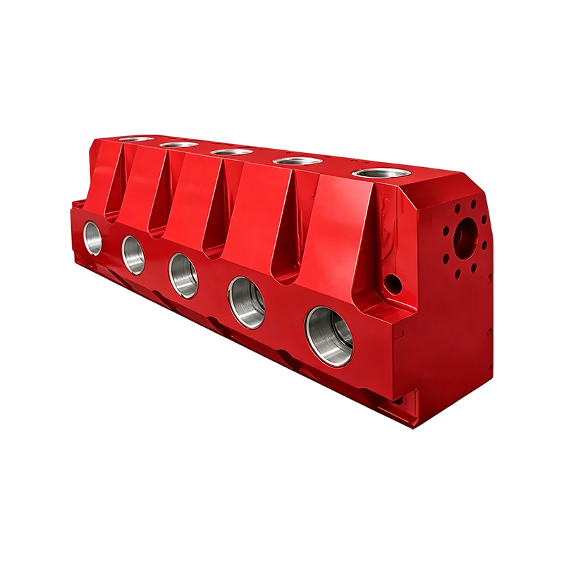
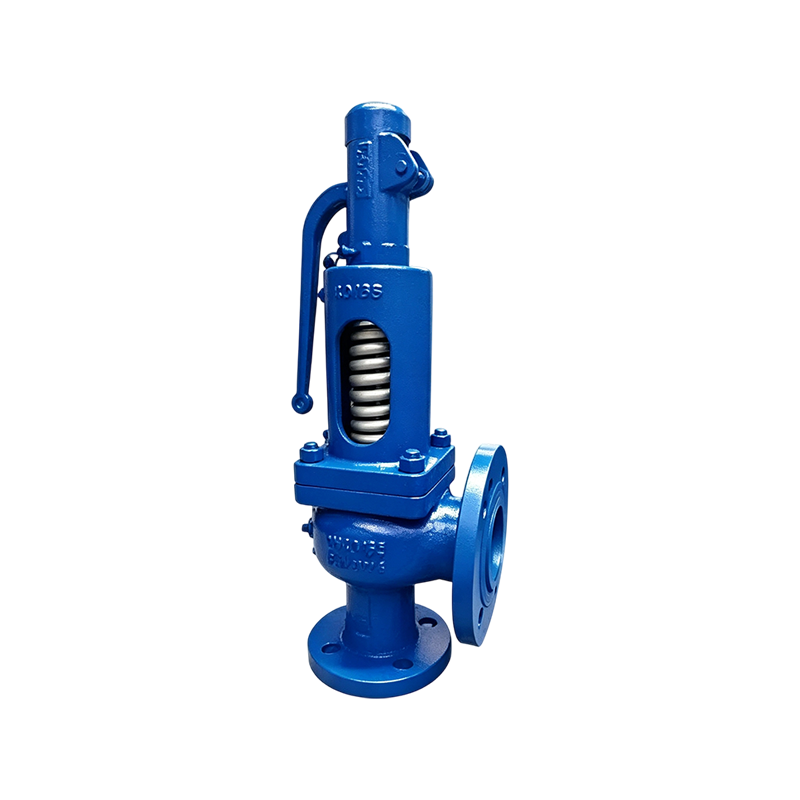
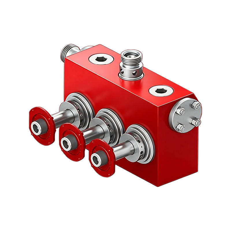
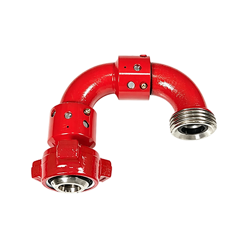
A FIG 1502 hammer union carries a 15,000 psi (103.4 MPa) working pressure rating and a FIG 602 elbow carries 6,000 psi (41.4 MPa). On a pipe rack the two look close enough that a crew can make them ...
READ MOREW Industrial Oilfield Equipment Parts Manufacturer: A Buyer's Sourcing Guide
Content
- 1 What an Industrial Oilfield Equipment Parts Manufacturer Supplies
- 2 The Five Specifications That Decide Whether a Part Fits
- 3 Matching Pump Families to Field Applications
- 4 Pressure Classes: Where the Standard Stops and Engineering Begins
- 5 Distributor or Manufacturer: What Actually Changes
- 6 Lead Time, Traceability and the Cost of a Shutdown
- 7 Custom Fluid End Assemblies: When Interchange Is Not Enough
- 8 Qualifying a Supplier in Two Weeks
- 9 Practical Questions Before a First Order
When a cementing crew pulls a triplex plunger pump out of service at 04:00, the number that decides the day is not the pump's duty cycle. It is the hours between the failure report and the moment a replacement fluid end, valve and seat set, or power end wear component is on site and dimensionally correct.
Procurement teams sourcing from a trading desk and teams sourcing from a factory live with two very different versions of that number. Anhui Exwell New Energy Technology Co., Ltd. is one example of the factory model: a 20-acre manufacturing base in Wuhu, Anhui Province, USD 85.7 million in reported annual output, USD 34.2 million exported, and a product line built around the fluid end, power end and manifold hardware that well service and fracturing spreads consume.
An industrial oilfield equipment parts manufacturer fabricates, machines and assembles the wear and structural components used inside oilfield high-pressure pumps and the manifolds that feed them — fluid ends, power ends, mud pump housings, plungers, valves, seats and API-specification flow-control fittings — rather than operating the wells those components serve.
What an Industrial Oilfield Equipment Parts Manufacturer Supplies
A qualified parts manufacturer ships five component families, and each one carries a different failure mode, lead time and documentation requirement.
- Fluid end assemblies and consumables: complete bodies plus the plungers, packing, valve and seat sets that wear on a predictable cycle.
- Power end wear components: crankshafts, connecting rods, crossheads, pinion shafts and bearing sets sized to a specific pump frame.
- Mud pump assemblies and housings: triplex plunger mud pumps, F-series pumps and fluid end housing assemblies for drilling and circulation service.
- High-pressure flow control: elbows, tees, crosses, Y-shaped manifold joints, plug valves, throttle valves, hammer unions and swivel joints rated from 42 MPa to 105 MPa.
- Custom assemblies: fluid ends and housings built to a customer drawing when the original casting or forging is obsolete.
The line between a parts catalog and a parts manufacturer runs through item five. A distributor can quote from a list; only a manufacturer can open the drawing, change the bore or the flange pattern, and re-machine the part.
Most manifold hardware follows the FIG naming convention from API Spec 6A, and a FIG 1502 fitting is not interchangeable with a FIG 602 fitting at any pressure. The published high-pressure manifold, valve and union range is usually the fastest way to confirm which FIG class a specific item carries.
The Five Specifications That Decide Whether a Part Fits
Five specifications decide fit: working-pressure class, fluid end bore and plunger diameter, power end stroke and gear ratio, material and heat treatment, and connection standard. Get any one wrong and the part arrives, bolts up, and fails.
| Specification | Typical reference | What a mismatch costs |
| Working pressure class | API 6A / API 16C: FIG 602 at 6,000 psi, FIG 1002 at 10,000 psi, FIG 1502 at 15,000 psi | Sealing faces will not hold rated pressure and wing unions will not seat |
| Fluid end bore and plunger diameter | Model-specific: HT400, TWS600S, QWS1000, QWS2500, QWS2800 | Packing fails within hours and the fluid end body cannot be reused |
| Power end stroke and gear ratio | Model-specific crank, pinion and crosshead geometry | Wear components bind and load the gear train beyond design limits |
| Material and heat treatment | Forged alloy steel to the pump maker's drawing; NACE MR0175 / ISO 15156 for sour service | Stress cracking in H2S service, often before the first inspection interval |
| Connection standard | Hammer union, flange or threaded joint per API Spec 6A | The part cannot be joined to existing iron already on location |
Matching Pump Families to Field Applications
Pump family selection follows the job, not the catalog. HT400 fluid ends serve cementing units, TWS600S offset plunger pumps serve acidizing and fracturing, the QWS quintuplex line serves well service and hydraulic fracturing, and JWS400 and 7P50 units move drilling mud.
| Pump family | Primary field application | Parts reordered most often |
| HT400 triplex | Oilfield cementing equipment | Fluid end assembly, valve and seat sets, plungers |
| TWS600S offset plunger | Acidizing and fracturing, compact well service | Packing sets, plungers, power end wear parts |
| TWS2250 triplex | Well stimulation, deep-well high-pressure injection | Fluid end, crosshead and pinion components |
| QWS1000 / QWS2500 quintuplex | Hydraulic fracturing and well service | Fluid end assembly, power end wear components |
| JWS400 horizontal triplex | Drilling mud and well service | Fluid end housing, power end components |
| 7P50 high pressure | Oilfield circulation system | Pump housing and fluid end |
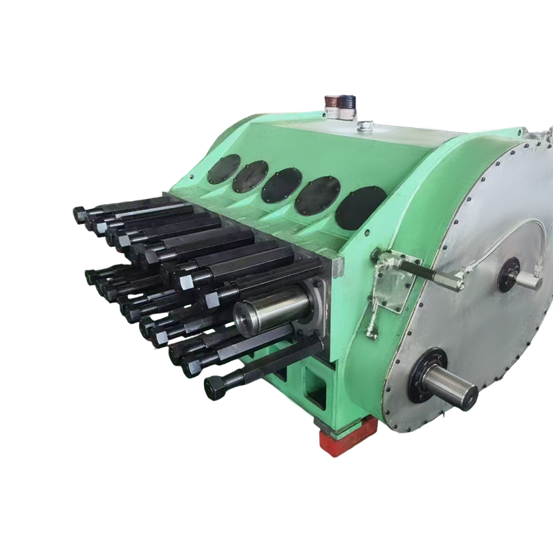 QWS2500 High‑Pressure Heavy‑Duty Quintuplex Fracturing PumpProduct Overview The QWS2500 Triplex Pump is a high‑power three‑plunger pump dedicated to oilfield fracturing. It adopts an 8‑inch stroke and 6.353:1 gear ratio, with ...View Product →
Pressure Classes: Where the Standard Stops and Engineering Begins
API Spec 6A defines the pressure classes — FIG 602 at 6,000 psi, FIG 1002 at 10,000 psi and FIG 1502 at 15,000 psi — but the standard does not tell you which class a given fracturing spread should carry. That decision belongs to the service company, and it is the first thing a parts manufacturer should confirm in writing.
API Spec 6A figure (FIG) working-pressure classes
FIG 602
FIG 1002
FIG 1502
Bar length is proportional to rated working pressure. The three classes correspond to 41.4 MPa, 69.0 MPa and 103.4 MPa, which is why supplier catalogs quote a 42 MPa to 105 MPa elbow and swivel-joint range.
103.4 MPa Working pressure of a FIG 1502 manifold joint at 15,000 psi
PSL 3 Common pressure and temperature rating level for fracturing manifold service
PR2 Performance requirement level for cyclic loading under API Spec 6A
API 6A pressure and temperature rating levels run from PSL 1 to PSL 4, and performance requirements from PR1 to PR2. Fracturing and well-service manifolds are commonly specified at PSL 3 with PR2 performance requirements, which means the hardware has been qualified for cyclic rather than static loading. A supplier that cannot state its PSL and PR level in writing is not a supplier to put on a 15,000 psi line.
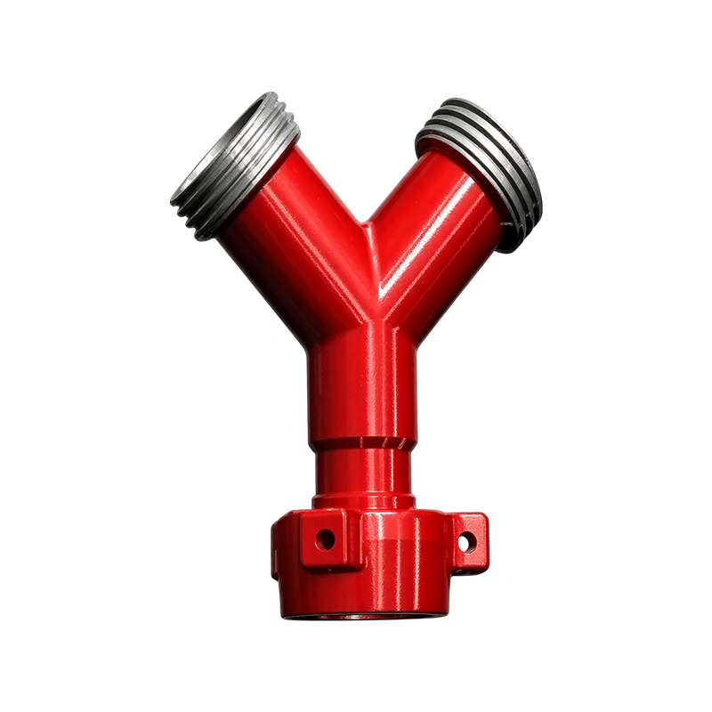 FIG 602/1002/1502 High-Pressure Integral Y-Shaped Manifold JointWorking pressure: 42MPa-105MPa(6000psi–15000psi)View Product →
Distributor or Manufacturer: What Actually Changes
Buying direct from a manufacturer changes three things: drawing access, minimum order quantity, and the speed at which a non-standard modification can be engineered. Price per piece converges once volume is high enough.
Through a distributor
- Fast availability on catalog items already in regional stock
- Little visibility into the original drawing or heat lot
- Non-standard modifications are usually declined
- Multiple brands consolidated onto one invoice
Direct from a manufacturer
- Drawing and tolerance data available on request
- Heat-lot traceability back to the melt
- Custom bores, flange patterns and materials feasible
- Longer first-article lead time, shorter repeat lead time
The working rule: source catalog consumables wherever lead time is shortest, and source pressure-containing assemblies plus any non-standard geometry directly from the factory that machines them.
Lead Time, Traceability and the Cost of a Shutdown
Every pressure-containing part should arrive with three documents: a material test report to EN 10204 3.1, a dimensional inspection record, and a hydrostatic test certificate at 1.5 times rated working pressure. API Spec 6A requires that hydrostatic shell test, and a supplier treating it as optional is telling you something about the rest of the process.
A fluid end that fails a 22,500 psi shell test inside the factory is a warranty claim. The same fluid end that fails it on location is a lost stage.
Traceability is the second half of the same argument. A manufacturer that can produce the heat lot number for a forged fluid end can also state the alloy, the heat treatment cycle and the hardness range that part was verified against. That matters most in sour service, where NACE MR0175 / ISO 15156 limits carbon and low-alloy steels to 22 HRC maximum hardness in H2S-containing environments.
Custom Fluid End Assemblies: When Interchange Is Not Enough
Custom manufacturing becomes necessary in three situations: the original pump model is out of production, the field application pushes beyond the original pressure class, or the operator wants a consumable package that combines parts from more than one platform.
The workflow is unglamorous. Send the failed part or a full dimensional drawing, confirm the mating geometry against the iron it will bolt to, agree on material and heat treatment, and approve a first article before the batch runs. A plant with in-house machining can typically run a non-standard first article inside the same window as a standard catalog order, provided the drawing is legible and the pressure class is stated.
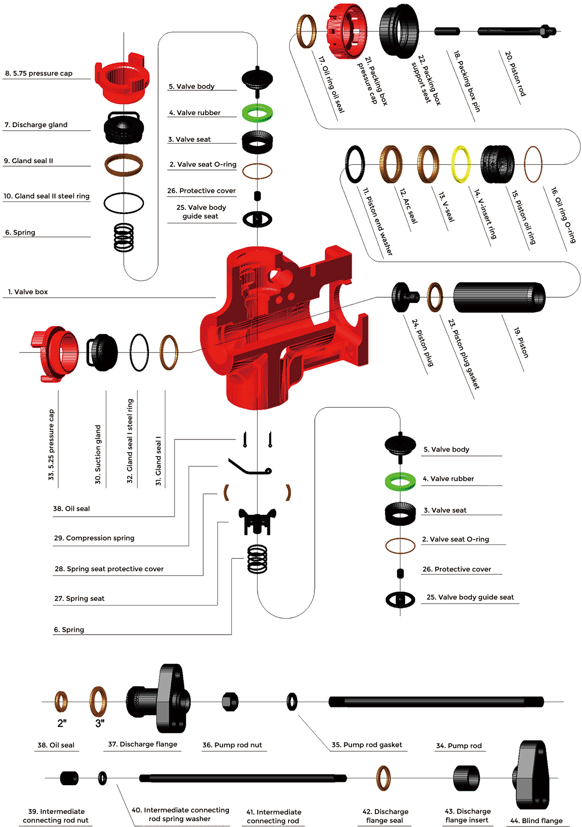 HT400 Fluid End AssemblyWe provide 3–5 inch replacement parts for Halliburton HT400 plunger pumps. All interchangeable spare parts meet OEM quality standards. And we accept custom parts built...View Product →
The cost case is rarely the part price itself. On a well service spread, one unplanned trip to replace a mismatched fluid end consumes more budget than the premium on a correctly specified custom assembly. Teams that run cementing and acidizing spreads should read up on fluid end maintenance and replacement planning before the next rebuild cycle starts.
Qualifying a Supplier in Two Weeks
A two-week qualification window is realistic when the buyer drives it with documentation rather than site visits.
- Send a parts list naming the pump model, the serial number where available, and the measured dimensions of the failed component.
- Request the drawing or dimensional inspection report for the proposed replacement and compare it against the failed part.
- Ask for the material specification and heat treatment record, including hardness verification for any sour-service item.
- Confirm the working pressure class and connection standard in writing — FIG number, PSL level and PR level, not a verbal assurance.
- Place a first order small enough to inspect properly: one or two assemblies, not a season of consumables.
Practical Questions Before a First Order
What separates an OEM part from an OEM-quality replacement?
The difference is drawing control and liability, not metallurgy. A replacement built to the same drawing, alloy and hardness specification interchanges dimensionally; what differs is who warrants the fit. Ask for the dimensional report and the material certificate, and write the FIG class into the purchase order.
What pressure class should a fracturing manifold carry?
FIG 1502 at 15,000 psi, equal to 103.4 MPa, is the working class for most hydraulic fracturing manifolds, commonly specified at API 6A PSL 3 with PR2 performance requirements. Lower classes such as FIG 602 at 6,000 psi remain appropriate for cementing and lower-pressure circulation service.
How much fluid end inventory should a well service spread hold?
Enough to cover the longest realistic resupply window, which for imported parts is measured in weeks rather than days. A spread running continuous operations should hold at least one complete fluid end assembly plus valve and seat sets, because a fluid end is a pressure boundary and cannot be repaired on location.
Can a non-standard fluid end be reverse engineered from a worn sample?
Yes, provided the sample retains enough dimensional integrity to measure. Reverse engineering works when the bore, flange faces and mounting pattern are still measurable within tolerance. If the body is cracked or eroded past the wall thickness, the manufacturer will need the original drawing or a working reference part instead.
Recommended Products
-
High Pressure Quintuplex Pump QWS2500 Parts for Oilfield Well Service
-
Triplex Plunger Pump HT400 Spare Parts for Oilfield Cementing Equipment
-
QWS2800 High Pressure Quintuplex Pump Fluid End Assembly for Oilfield Well Service
-
API Standard Pressure Safety Relief Valves for Industrial Boilers
-
Offset Plunger Pump TWS600S Spare Parts for Acidizing and Fracturing
-
2" to 4" Long Radius Bend 50 Swivel Joint for High-Pressure Oilfield Equipment
News
-
-
Why Fluid End Condition Determines Triplex Pump Uptime On any well service location, the pressure-containing components inside a fluid end absorb more cyclic stress than almost any other part of the ...
READ MORE -
WELL SERVICE EQUIPMENT JWS-400 Triplex Pump at a Glance The JWS-400 is a single-acting triplex reciprocating pump designed for high-pressure, intermittent-duty well service operations. Published tech...
READ MORE -
Ask a field supervisor what puts a triplex pump on the ground, and the answer almost always points to the fluid end. A plunger washes out, packing starts weeping, a valve seat stops sealing, and a sm...
READ MORE
Get in Touch
Your email address will not be published.
Required fields are marked *
contact us
Have a project in mind?
Contact with us
Contact with us
We are happy to answer your questions. Please fill out this form
and one of our professional team will get back to you as soon as possible.

-
Company AddressRoom 2112, Wanxi Jingyuan Building 10, Jichuan Subdistrict, west of Wanxi South Road and north of Diefeng East Road, Xuanzhou District, Xuancheng City, Anhui Province
-
Tel:+86-13063235523
-
E-mail:Exwell.sales@chinafluidendparts.com
Exwell.Petro@chinafluidendparts.com
Exwell.Director@chinafluidendparts.com
Exwell@chinafluidendparts.com
Copyright © Anhui Exwell New Energy Technology Co., Ltd. All Rights Reserved.
OEM High Pressure Drilling Equipment Suppliers
