
 English
 عربى
عربى русский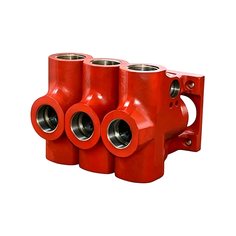
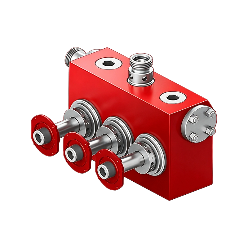
Why Fluid End Condition Determines Triplex Pump Uptime On any well service location, the pressure-containing components inside a fluid end absorb more cyclic stress than almost any other part of the ...
READ MOREJWS-400 Triplex Well Service Pump: Specifications, Applications, and Spare Parts
Content
- 1 JWS-400 Triplex Pump at a Glance
- 2 JWS-400 Specifications and Mechanical Configuration
- 3 How Pump Size Affects Flow and Pressure
- 4 What Are the Main Sections of a JWS-400?
- 5 Fluid End: The Pressure-Handling Section
- 6 Why the Mud Pump Housing Matters
- 7 Power End: Converting Drive Power Into Reciprocating Motion
- 8 Which JWS-400 Spare Parts Usually Require the Most Attention?
- 9 How to Build a Practical JWS-400 Maintenance Plan
- 10 Where Is the JWS-400 Used in Well Service Operations?
- 11 Fluid End Versus Power End: What Should Be Inspected?
- 12 JWS-400 Pump Configuration in Service Equipment
- 13 How to Select JWS-400 Spare Parts Correctly
- 14 What Information Should Be Included in a Spare Parts Request?
- 15 Key Takeaways for JWS-400 Pump Maintenance
- 16 Frequently Asked Questions
- 16.0.1 Q1: What type of pump is the JWS-400?
- 16.0.2 Q2: What is the rated power of the JWS-400?
- 16.0.3 Q3: What is the maximum working pressure of the JWS-400?
- 16.0.4 Q4: What is the stroke length of the JWS-400?
- 16.0.5 Q5: What is the difference between the Fluid End and Power End?
- 16.0.6 Q6: Which JWS-400 parts are commonly treated as wear parts?
- 16.0.7 Q7: Can JWS-400 spare parts be selected only by model number?
- 16.0.8 Q8: What applications are associated with the JWS-400?
WELL SERVICE EQUIPMENT
JWS-400 Triplex Pump at a Glance
The JWS-400 is a single-acting triplex reciprocating pump designed for high-pressure, intermittent-duty well service operations. Published technical documentation identifies a 400 horsepower rating, a 7 inch stroke, a maximum operating speed of 286 rpm, and a maximum working pressure of 10,000 psi. These characteristics place the pump in a class intended for demanding pressure-transfer duties where controlled fluid delivery and mechanical durability are important.
For equipment engineers, maintenance teams, and spare-parts buyers, understanding the pump as a complete mechanical system is more useful than looking at pressure or horsepower alone. The jws-400 triplex well service pump combines a power transmission section with a fluid-handling section, and each section has different inspection priorities.
400 HPRated input power
7 inStroke length
286 rpmMaximum speed
10,000 psiMaximum working pressure
JWS-400 Specifications and Mechanical Configuration
The basic specification set explains why the JWS-400 is used as a well service pump rather than as a general-purpose industrial transfer pump. Its relatively long 7 inch stroke provides the reciprocating displacement required for high-pressure service, while the triplex arrangement uses three cylinders to produce a more continuous discharge pattern than a single-cylinder arrangement.
Published technical data lists a maximum liner diameter of 5 1/2 inches and a maximum plunger diameter of 4 1/2 inches. The pump is rated at 400 horsepower at 286 rpm, equivalent to approximately 298 kW. The published pump weight with reducer is approximately 15,000 pounds, or 6,804 kg. Crankcase oil capacity is listed at 22 gallons, while the chaincase capacity is listed at 30 gallons.
| Parameter | Published specification | Engineering significance |
|---|---|---|
| Pump type | Triplex, single acting | Three-cylinder reciprocating fluid delivery |
| Rated input power | 400 HP / 298 kW | Defines the rated power class |
| Stroke length | 7 in / 177.8 mm | Determines reciprocating travel |
| Maximum speed | 286 rpm | Upper operating speed reference |
| Maximum working pressure | 10,000 psi | High-pressure service capability |
| Maximum liner diameter | 5 1/2 in / 139.7 mm | Relevant to piston configuration |
| Maximum plunger diameter | 4 1/2 in / 114.3 mm | Relevant to plunger configuration |
| Approximate weight with reducer | 15,000 lb / 6,804 kg | Important for skid and handling design |
These figures should be treated as reference specifications for the documented JWS-400 configuration. Actual operating limits should always be checked against the pump nameplate, service documentation, fluid-end configuration, pressure rating of connected equipment, and the operating conditions of the complete well service package.
How Pump Size Affects Flow and Pressure
A reciprocating well service pump does not operate at one fixed combination of pressure and flow. Changing the piston or plunger diameter changes displacement per stroke, while operating speed changes the number of strokes completed during a given period. At a given power level, increasing pressure generally reduces the flow that can be maintained within the available power envelope.
Published JWS-400 performance information provides piston displacement figures for several piston diameters. For example, the listed displacement per rpm rises from approximately 1.142 gallons per minute per rpm with a 4 inch piston to approximately 2.159 gallons per minute per rpm with a 5 1/2 inch piston. This illustrates why liner and piston selection must be considered together with the required pressure and flow range.
Relative Flow Capacity by Piston Diameter
The chart is intended to show the relationship between piston size and displacement, not to define a recommended operating point. Field operation must remain within the pressure, speed, temperature, fluid compatibility, and mechanical limits established for the complete pumping system.
What Are the Main Sections of a JWS-400?
The pump can be understood through two major mechanical zones: the power end and the fluid end. The power end converts rotary input into reciprocating movement. The fluid end transfers that movement into pressure and fluid displacement. Between them are intermediate rods, crossheads, and related sealing components that transmit motion while separating the lubricated mechanical section from the working fluid.
Fluid End: The Pressure-Handling Section
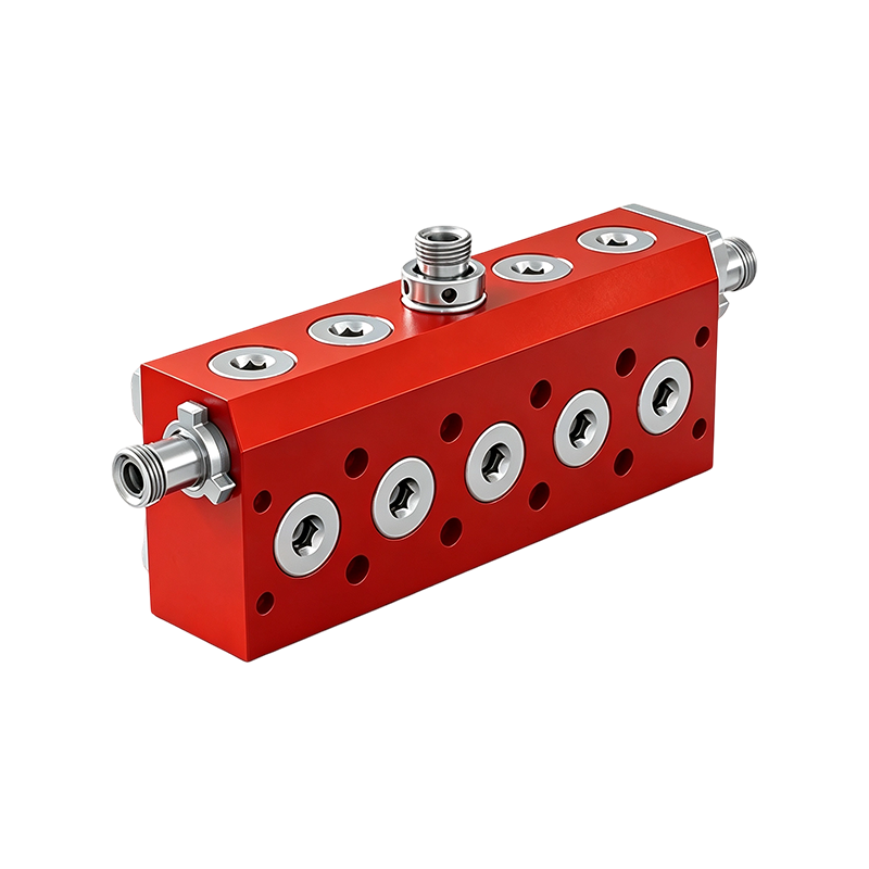
FLUID HANDLING
The fluid end is the part of the pump that directly interacts with the working fluid. It contains the cylinder passages, suction and discharge valve areas, seats, liners or plungers depending on configuration, and sealing interfaces. Because pressure cycles are concentrated in this area, inspection of wear surfaces and sealing components is a central maintenance activity.
Published JWS-400 documentation describes a forged steel fluid end and forged steel valve covers. The documented configuration also includes individually removable liners, piston and liner or plunger and packing arrangements, and serviceable valve components.
Components Commonly Associated With the Fluid End
- Fluid-end body or module
- Valve covers and associated sealing elements
- Valves and valve seats
- Lin ers or plunger assemblies according to configuration
- Piston or plunger packing components
- Stuffing boxes and glands
- Pressure-side connections and seals
Wear in the fluid end can be accelerated by abrasive solids, unsuitable fluid chemistry, inadequate lubrication of packing, poor suction conditions, or operation outside the intended pressure and speed range. A pressure problem should therefore not automatically be attributed to the pump body itself. Valve wear, seat damage, liner condition, packing leakage, and suction instability can all affect pumping performance.
Why the Mud Pump Housing Matters
STRUCTURAL SUPPORT
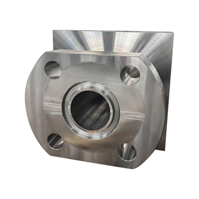
The mud pump housing provides the structural environment in which major pumping components are mounted and aligned. For maintenance planning, housing condition is important because bearing support, crankshaft alignment, cover interfaces, and mounting surfaces influence the mechanical behavior of the complete assembly.
A housing inspection should look beyond visible corrosion. Engineers should consider cracks, damaged mounting surfaces, abnormal fretting, loose fasteners, oil leakage, contamination, and evidence of misalignment. Any structural defect should be evaluated against the applicable repair criteria rather than corrected through an improvised field modification.
Maintenance principle
Structural components do not normally receive the same replacement frequency as valves, packing, liners, or other wear parts. Their inspection is therefore better treated as a condition-based activity supported by dimensional checks and documented maintenance history.
Power End: Converting Drive Power Into Reciprocating Motion
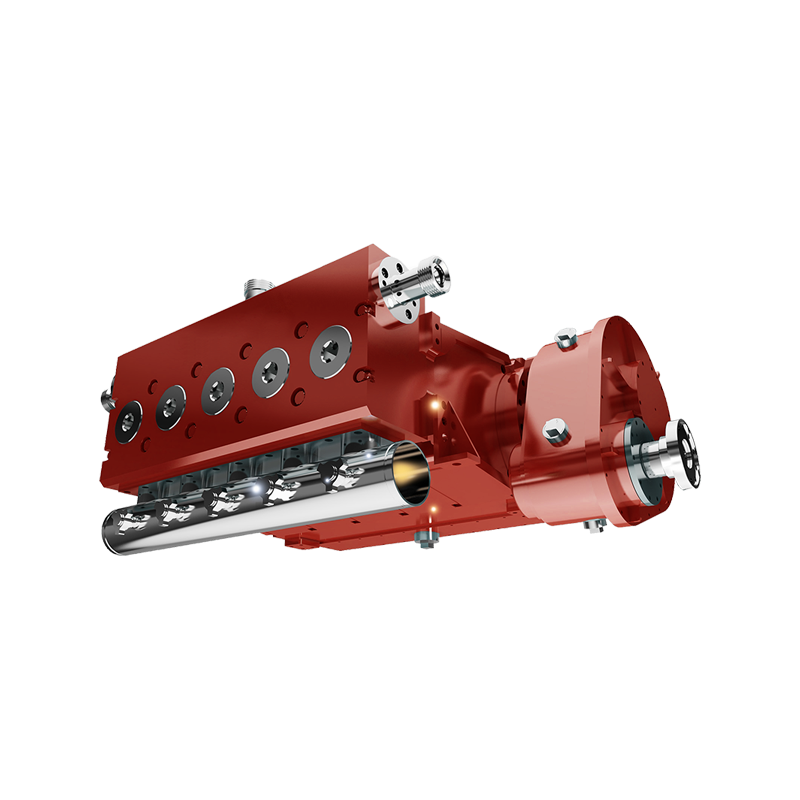
POWER TRANSMISSION
The power end contains the mechanical components responsible for transmitting drive input to the three reciprocating pumping elements. Published documentation identifies a high-strength steel frame, tapered roller crankshaft bearings, crankpin bearings, connecting rods, cast iron crossheads, intermediate rods, and an oil-lubricated mechanical section.
The crankshaft converts rotary movement into the reciprocating movement required by the crossheads. Intermediate rods then transmit this movement toward the fluid end. Correct lubrication and alignment are essential because bearing loads and reciprocating forces are continuously transferred through this section.
Power End Inspection Priorities
- Check lubricant level and contamination condition.
- Inspect bearings for abnormal noise, heat, wear, or looseness.
- Inspect crankshaft and crankpin areas during scheduled maintenance.
- Check connecting rods and intermediate rods for visible damage.
- Inspect crossheads and related sliding surfaces for abnormal wear.
- Check covers, breathers, seals, and mounting interfaces for leakage or damage.
Which JWS-400 Spare Parts Usually Require the Most Attention?
Spare-parts planning should separate routine wear components from major structural components. The purpose is not simply to maintain a large inventory, but to ensure that components with predictable wear or long procurement cycles can be replaced without extending equipment downtime.
01Fluid-End Wear Parts
Valves, seats, packing, liners, pistons, plungers, and related sealing parts can require periodic inspection or replacement.
02Power-End Parts
Bearings, crosshead components, rods, gaskets, seals, and lubrication-related parts support mechanical reliability.
03Connection Parts
Pressure connections, covers, seals, and associated hardware should match the specified configuration and service rating.
04Maintenance Tools
Valve service and seat-removal equipment can reduce maintenance delays when compatible with the installed configuration.
Historical JWS-400 parts documentation lists power-end assemblies, intermediate rods, crosshead covers, gaskets, breathers, oil troughs, and other mechanical components. Separate fluid-end parts documentation covers pumping and valve-service components. This separation is useful when preparing a spare-parts list because power-end and fluid-end requirements should not be mixed into one generic kit.
How to Build a Practical JWS-400 Maintenance Plan
A useful maintenance plan combines operating observations with scheduled inspections. Pressure, discharge stability, leakage, vibration, lubricant condition, and unusual noise can provide early indications of component deterioration. Maintenance intervals should be established according to operating severity, fluid characteristics, duty cycle, and the equipment manufacturer's service requirements.
Before operationInspect fluid connections, lubrication level, guards, leaks, and visible component condition.
During operationMonitor pressure, discharge behavior, vibration, temperature, leakage, and abnormal noise.
Scheduled serviceInspect valves, seats, liners, packing, bearings, rods, crossheads, and lubrication systems.
Major inspectionEvaluate crankshaft, bearings, structural surfaces, fluid-end condition, and dimensional wear.
The most important maintenance distinction is between symptoms and causes. A fluctuating discharge pressure can originate from valve condition, suction problems, air entrainment, packing leakage, or changes in operating conditions. A hot bearing may reflect lubrication problems, alignment issues, overload, or bearing deterioration. Replacing a visible component without checking the underlying cause can shorten the service life of the replacement part.
Where Is the JWS-400 Used in Well Service Operations?
Published technical literature describes the JWS-400 as an intermittent-duty well service pump for high-pressure, high-horsepower applications. Listed service applications include reverse circulation, well killing, acidizing, cementing, and sand fracturing. These applications share a need for controlled movement of fluid at elevated pressure, but their fluid characteristics and operating profiles can be very different.
Typical Application Demand Profile
The chart is an engineering-oriented visualization rather than a measured performance ranking. Actual duty severity depends on pressure, fluid properties, solids content, temperature, duration, pumping schedule, and the configuration of the complete service unit.
Fluid End Versus Power End: What Should Be Inspected?
Both major sections are essential, but their failure mechanisms are different. The fluid end is exposed to the pumped medium and pressure cycling. The power end is primarily concerned with mechanical loads, lubrication, alignment, and motion transmission.
The comparison highlights why a complete spare-parts strategy should cover both sides of the pump. Fluid-end wear may become visible through leakage, pressure instability, or reduced pumping consistency, while power-end problems may first appear as vibration, abnormal temperature, lubricant contamination, or unusual mechanical noise.
JWS-400 Pump Configuration in Service Equipment
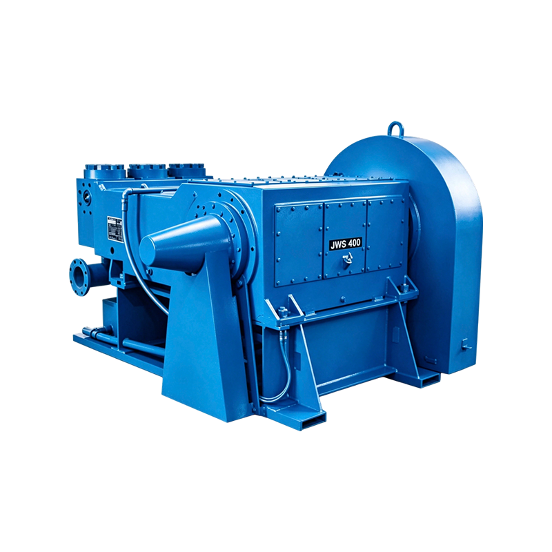
TRIPLEX WELL SERVICE PUMP
The complete pump should be evaluated as part of the well service package rather than as an isolated component. Drive equipment, suction equipment, discharge piping, pressure-control equipment, dampening devices, instrumentation, and skid structure all influence the operating environment experienced by the pump.
How to Select JWS-400 Spare Parts Correctly
Correct part selection begins with identifying the exact pump configuration. A request that only states JWS-400 may be insufficient when different fluid-end arrangements, piston or plunger configurations, connection requirements, or service histories are involved.
- Confirm the pump model and available nameplate information.
- Identify the fluid-end configuration and pressure rating.
- Confirm piston, liner, or plunger dimensions where applicable.
- Check valve and seat configuration before ordering replacements.
- Confirm power-end component identification and assembly location.
- Match seals, gaskets, and wear components to the actual assembly.
- Review drawings or parts documentation before final procurement.
For critical equipment, interchangeable appearance should never be treated as proof of compatibility. Dimensional fit, material suitability, pressure rating, connection geometry, and service conditions should all be verified. This is particularly important for pressure-containing fluid-end components and rotating power-end components.
Key Takeaways for JWS-400 Pump Maintenance
The JWS-400 is a high-pressure, intermittent-duty triplex well service pump with a documented 400 horsepower rating, 7 inch stroke, maximum speed of 286 rpm, and maximum working pressure of 10,000 psi. Its mechanical architecture divides naturally into the Power End, intermediate motion-transfer components, and Fluid End.
The Fluid End deserves close attention because it is directly exposed to pressure cycling and the pumped medium. Valves, seats, liners, pistons, plungers, packing, and seals are therefore important wear and maintenance items. The Power End requires a different inspection approach focused on bearings, crankshaft components, connecting rods, crossheads, lubrication, alignment, and structural condition.
For procurement teams, the most reliable spare-parts process starts with configuration identification rather than simply matching a product name. Combining model information, dimensions, assembly location, pressure requirements, and service conditions provides a stronger basis for compatibility assessment and maintenance planning.
Frequently Asked Questions
Q1: What type of pump is the JWS-400?
The JWS-400 is a triplex, single-acting, intermittent-duty reciprocating well service pump designed for high-pressure fluid pumping applications.
Q2: What is the rated power of the JWS-400?
Published technical documentation lists a rated input power of 400 horsepower, equivalent to approximately 298 kW.
Q3: What is the maximum working pressure of the JWS-400?
The published specification identifies a maximum working pressure of 10,000 psi. Actual operating pressure must also consider the installed fluid-end configuration and the pressure ratings of the complete connected system.
Q4: What is the stroke length of the JWS-400?
The documented stroke length is 7 inches, equivalent to approximately 177.8 mm.
Q5: What is the difference between the Fluid End and Power End?
The Fluid End contains the pressure and fluid-handling components, while the Power End converts rotary drive input into reciprocating mechanical movement and supports the associated mechanical loads.
Q6: Which JWS-400 parts are commonly treated as wear parts?
Commonly inspected wear components include valves, valve seats, packing, liners, pistons, plungers, seals, and related fluid-end components. Power-end bearings and motion-transfer components also require condition monitoring.
Q7: Can JWS-400 spare parts be selected only by model number?
Model identification is a starting point, but it may not be sufficient. The exact fluid-end configuration, dimensions, component arrangement, pressure requirements, and service conditions should also be verified.
Q8: What applications are associated with the JWS-400?
Published technical material associates this pump class with well service operations including reverse circulation, well killing, acidizing, cementing, and sand fracturing. Actual suitability depends on the complete pumping system and operating conditions.
Recommended Products
-
Triplex Plunger Pump HT400 Spare Parts for Oilfield Cementing Equipment
-
Triplex Frac Pump TWS2250 Replacement Parts for Well Stimulation
-
JWS400 Horizontal Triplex High-Pressure Drilling Mud Pump
-
TWS600S Compact‑Structure Multifunctional Triplex Well Service Pump
-
High Pressure Quintuplex Pump QWS2500 Parts for Oilfield Well Service
-
Offset Plunger Pump TWS600S Spare Parts for Acidizing and Fracturing
News
-
-
Understanding the Power End in a Triplex Well Service Pump The power end is the mechanical core of any triplex well service pump. It is the assembly responsible for converting rotational input from ...
READ MORE -
Understanding the Role of a Mud Pump Housing in Well Service Systems A mud pump housing is the structural core of any reciprocating well service pump. It is the component that carries the full weigh...
READ MORE
Get in Touch
Your email address will not be published.
Required fields are marked *
contact us
Have a project in mind?
Contact with us
Contact with us
We are happy to answer your questions. Please fill out this form
and one of our professional team will get back to you as soon as possible.

-
Company AddressRoom 2112, Wanxi Jingyuan Building 10, Jichuan Subdistrict, west of Wanxi South Road and north of Diefeng East Road, Xuanzhou District, Xuancheng City, Anhui Province
-
Tel:+86-13063235523
-
E-mail:Exwell.sales@chinafluidendparts.com
Exwell.Petro@chinafluidendparts.com
Exwell.Director@chinafluidendparts.com
Exwell@chinafluidendparts.com
Copyright © Anhui Exwell New Energy Technology Co., Ltd. All Rights Reserved.
OEM High Pressure Drilling Equipment Suppliers
