
 English
 عربى
عربى русский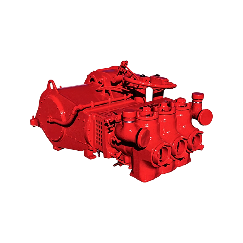
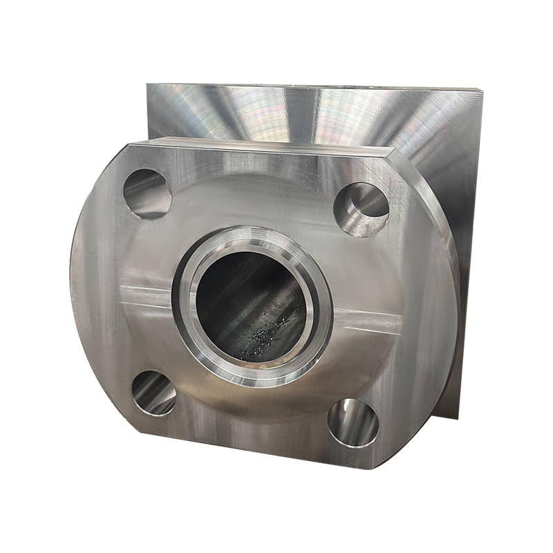
Why Fluid End Condition Determines Triplex Pump Uptime On any well service location, the pressure-containing components inside a fluid end absorb more cyclic stress than almost any other part of the ...
READ MOREPower End Components: How to Keep Your JWS-400 Pump Running at Peak Performance
Content
- 1 Understanding the Power End in a Triplex Well Service Pump
- 2 How the JWS-400 Power End Is Engineered for Continuous Duty
- 3 Core Components of the Power End and Their Function
- 4 Load Transfer Through the Crankshaft and Connecting Rod
- 5 Common Failure Modes and Root Causes
- 6 Lubrication and Thermal Management Under Continuous Load
- 7 A Practical Inspection and Maintenance Workflow
- 8 Comparing Duty Ratings Across Service Configurations
- 9 Wear Progression Across Cumulative Runtime
- 10 Best Practices for Extending Power End Service Life
- 11 Frequently Asked Questions
- 11.0.1 Q1: What is the difference between the power end and the fluid end of a triplex pump?
- 11.0.2 Q2: How often should the crankshaft and connecting rod be inspected?
- 11.0.3 Q3: What is the most common early sign of power end bearing wear?
- 11.0.4 Q4: Does a higher duty rating always mean better performance?
- 11.0.5 Q5: Can lubricant quality alone significantly affect power end service life?
Understanding the Power End in a Triplex Well Service Pump
The power end is the mechanical core of any triplex well service pump. It is the assembly responsible for converting rotational input from a prime mover into the linear, reciprocating motion that drives the plungers on the fluid end. Everything downstream of the power end, from pressure output to stroke consistency, depends on how well this assembly manages load, alignment, and lubrication over thousands of operating hours.
In well service applications such as cementing, acidizing, fracturing support, and coiled tubing operations, the power end is subjected to cyclic loading that changes constantly with pumping pressure, fluid density, and duty cycle. Unlike a continuous rotary machine, a triplex power end experiences a repeated load reversal on every stroke, which places fatigue resistance and precision fit at the center of its design requirements.
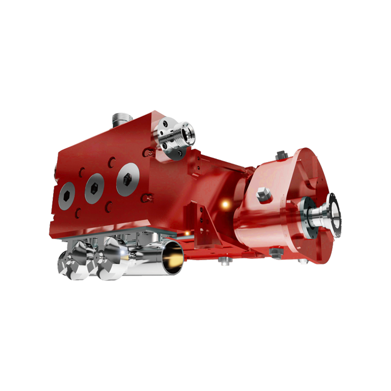
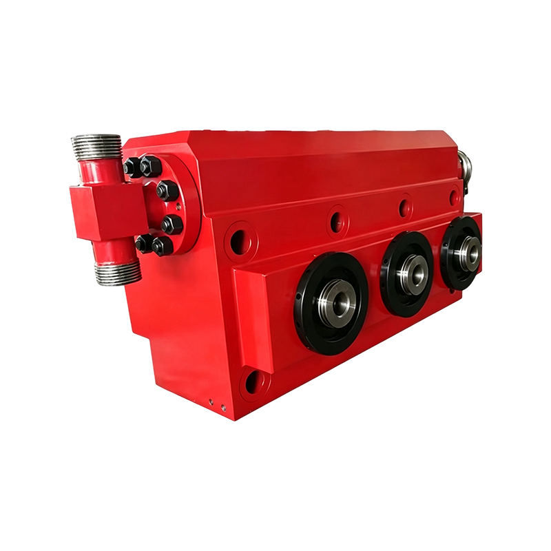
A power end assembly showing the crankshaft housing, connecting rod access covers, and crosshead extension section
A properly engineered power end does three things simultaneously: it transmits torque smoothly, it converts that torque into a controlled reciprocating stroke, and it isolates the rotating components from the pressurized fluid side of the pump. When any one of these functions degrades, the effects show up as increased vibration, uneven plunger load, or accelerated bearing wear long before a catastrophic failure occurs.
How the JWS-400 Power End Is Engineered for Continuous Duty
The jws-400 triplex well service pump is built around a power end structure sized for repeated, high-cycle service rather than intermittent use. The frame and crankcase are designed as a single rigid load path, which reduces the flexing that would otherwise concentrate stress at bolted joints and bearing bores during peak stroke pressure.
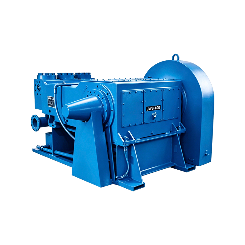
JWS-400 triplex well service pump configured for continuous field duty
Three design priorities shape how this power end behaves under load:
- Load capacity margin above the rated working pressure, so peak transient loads during valve closure do not push components past their fatigue threshold
- Bearing bore geometry that maintains consistent clearance across a wide operating temperature range
- A lubrication path that reaches the crankshaft, connecting rod bearings, and crosshead guides without relying on splash lubrication alone at low stroke speeds
These priorities matter because a well service pump rarely runs at a single fixed speed. Operators frequently ramp pressure up and down during a single job, and the power end has to tolerate that variability without a measurable change in bearing clearance or stroke timing.
Core Components of the Power End and Their Function
Each component in the power end plays a distinct mechanical role. Understanding what each part does makes it easier to interpret early warning signs during routine inspection, rather than waiting for a component to fail outright.
| Component | Function | Typical Inspection Interval |
|---|---|---|
| Crankshaft | Converts rotational torque into reciprocating motion for each plunger | Every 500 operating hours |
| Connecting Rod | Transfers force from the crankshaft to the crosshead assembly | Every 500 operating hours |
| Crosshead | Guides the reciprocating motion in a straight line and absorbs side loading | Every 250 operating hours |
| Main and Rod Bearings | Support rotating and reciprocating loads while minimizing friction | Every 250 operating hours |
| Frame and Crankcase | Provides the rigid structural housing that maintains component alignment | Every 1000 operating hours |
Of these, the crankshaft and connecting rod carry the highest cyclic stress, since they absorb the full reversal of load on every stroke. This is why most condition-monitoring programs weight their inspection frequency and data logging toward these two components.
Load Transfer Through the Crankshaft and Connecting Rod
Load does not distribute evenly across the power end. The crankshaft experiences the highest relative stress because it is the single point through which torque from the prime mover is converted into the force applied to every plunger. The connecting rod and bearings follow closely behind, while the frame and housing experience comparatively lower relative stress since their role is structural support rather than direct force transmission.
This pattern explains why crankshaft and connecting rod condition are the two most closely tracked variables in a well-run maintenance program. A power end can tolerate minor wear in the frame or housing for a long service period, but the same degree of wear on the crankshaft journal or connecting rod bearing translates directly into vibration, noise, and eventually a measurable loss of stroke accuracy.
Common Failure Modes and Root Causes
Most power end failures do not happen suddenly. They develop gradually through a small number of recurring root causes, and recognizing the early symptoms allows a failure to be addressed as a scheduled repair rather than an unplanned shutdown.
Field observation: in continuous duty applications, bearing-related issues account for a disproportionate share of unplanned power end downtime compared to structural or frame-related issues, largely because bearing wear is harder to detect visually before it affects clearance.
| Failure Mode | Typical Root Cause | Early Warning Sign |
|---|---|---|
| Bearing surface wear | Contaminated or degraded lubricant | Rising operating temperature at the bearing housing |
| Connecting rod fatigue cracking | Sustained overload beyond rated pressure | Localized vibration at stroke reversal points |
| Crosshead guide wear | Misalignment between crosshead and frame bore | Uneven wear pattern across the guide surface |
| Fastener loosening | Thermal cycling without re-torque verification | Audible knocking during load transitions |
Each of these failure modes shares a common trait: the symptom appears well before the failure becomes functionally significant, provided the inspection interval is short enough to catch it. This is why fixed inspection schedules, rather than run-to-failure practices, remain the standard approach for triplex power ends in well service duty.
Lubrication and Thermal Management Under Continuous Load
Critical Component Lubrication quality has an outsized effect on power end service life because it directly governs the operating temperature of the crankshaft and connecting rod bearings. As duty cycles extend and pressure ramps continue, bearing temperature typically rises through the first several hours of operation before stabilizing at a plateau that reflects the balance between generated friction heat and the cooling capacity of the lubrication system.
The plateau and slight decline shown in the later hours typically reflects the lubrication system reaching thermal equilibrium, provided the lubricant is clean and at the correct fill level. When temperature continues climbing rather than stabilizing, it is usually a sign of degraded lubricant viscosity, restricted flow to a specific bearing, or a developing clearance issue that is generating additional friction heat.
Routine Check Lubricant sampling at scheduled intervals, combined with a simple temperature log at the bearing housings, gives an early indication of drift long before vibration or noise becomes noticeable to an operator on site.
A Practical Inspection and Maintenance Workflow
Consistency matters more than complexity when it comes to power end maintenance. A short, repeatable workflow that is actually followed on every shift produces better long-term results than an elaborate schedule that gets skipped under field pressure.
The value of this workflow comes from the decision point at the end of each cycle. Rather than treating maintenance as a binary pass or fail, the wear-within-limits check allows the crew to keep the pump running when readings are inside the expected range, while routing anything outside that range into a scheduled service window rather than letting it run to failure.
Comparing Duty Ratings Across Service Configurations
Not every power end configuration is built for the same operating envelope. A standard duty configuration is well suited to intermittent well service work, while an extended duty configuration is designed for continuous, high-cycle operation across longer job durations. The difference shows up across several rated criteria rather than in a single specification.
The extended duty configuration consistently rates higher across every criterion, but the gap is not uniform. The largest difference typically appears in fatigue life and maintenance interval, which reflects a heavier crankshaft section and upgraded bearing specification rather than a change in peak pressure rating alone. Selecting between these configurations should be based on expected duty cycle length and job frequency rather than pressure rating in isolation.
Wear Progression Across Cumulative Runtime
Component wear on a power end does not progress linearly across its service life. Early hours typically show a slower rate of wear as components complete a break-in period, followed by a more consistent wear rate through the mid-life of the assembly, and finally an accelerating rate as clearances widen and load distribution becomes less even.
The steeper increase between 5000 and 7500 hours is the reason most maintenance programs shorten their inspection interval as a power end approaches its mid-to-late service life, rather than keeping a fixed interval for the entire operating lifespan of the assembly.
Best Practices for Extending Power End Service Life
The practices that extend the working life of a power end assembly tend to be procedural rather than technical. Consistency in application matters more than any single upgrade in component quality.
- Track lubricant condition through scheduled sampling rather than relying on fill level alone
- Log bearing temperature at consistent intervals so gradual drift can be identified before it becomes a failure
- Re-torque structural fasteners after the first operating cycles following any major service event
- Shorten inspection intervals as cumulative runtime hours increase, particularly past the midpoint of expected service life
- Avoid sustained operation above rated pressure, even for short periods, since peak loads disproportionately affect connecting rod fatigue life
None of these practices require specialized equipment. What they require is a consistent record over time, so that a rising trend in temperature, vibration, or wear can be caught while it is still a scheduled maintenance item rather than an unplanned failure in the field.
Frequently Asked Questions
Q1: What is the difference between the power end and the fluid end of a triplex pump?
The power end houses the crankshaft, connecting rods, and bearings that generate reciprocating motion. The fluid end is the pressurized side that contains the plungers, valves, and pumped fluid. The power end drives the fluid end but is mechanically isolated from direct contact with the pumped fluid.
Q2: How often should the crankshaft and connecting rod be inspected?
A common interval is every 500 operating hours, though this should be shortened as cumulative runtime increases, particularly once the assembly passes the midpoint of its expected service life.
Q3: What is the most common early sign of power end bearing wear?
A gradual rise in bearing housing temperature is typically the earliest measurable sign, often appearing before vibration or audible noise becomes noticeable.
Q4: Does a higher duty rating always mean better performance?
A higher duty rating generally means better tolerance for continuous, high-cycle operation, but it should be matched to actual job requirements. An extended duty configuration offers little practical benefit if the pump is only used intermittently.
Q5: Can lubricant quality alone significantly affect power end service life?
Yes. Since bearing temperature and wear rate are closely tied to lubricant condition, degraded or contaminated lubricant is one of the most common root causes of accelerated power end wear.
Recommended Products
-
JWS400 Horizontal Triplex High-Pressure Drilling Mud Pump
-
Heavy Duty Triplex Pump HT400 Wear Components for Oil & Gas Field
-
TWS3000 Heavy-Duty Triplex Pump Fluid End.
-
High Pressure P Series Mud Pump for Oilfield Circulation System
-
HT400 Fluid End Assembly
-
Fluid End Housing Assembly for Triplex Mud Pump
News
-
-
WELL SERVICE EQUIPMENT JWS-400 Triplex Pump at a Glance The JWS-400 is a single-acting triplex reciprocating pump designed for high-pressure, intermittent-duty well service operations. Published tech...
READ MORE -
Understanding the Role of a Mud Pump Housing in Well Service Systems A mud pump housing is the structural core of any reciprocating well service pump. It is the component that carries the full weigh...
READ MORE -
Founded in 2019, Anhui Exwell New Energy Technology Co., Ltd. is a professional supplier specializing in spare parts for the global petroleum industry. Headquartered in Anhui Province with a 20-a...
READ MORE
Get in Touch
Your email address will not be published.
Required fields are marked *
contact us
Have a project in mind?
Contact with us
Contact with us
We are happy to answer your questions. Please fill out this form
and one of our professional team will get back to you as soon as possible.

-
Company AddressRoom 2112, Wanxi Jingyuan Building 10, Jichuan Subdistrict, west of Wanxi South Road and north of Diefeng East Road, Xuanzhou District, Xuancheng City, Anhui Province
-
Tel:+86-13063235523
-
E-mail:Exwell.sales@chinafluidendparts.com
Exwell.Petro@chinafluidendparts.com
Exwell.Director@chinafluidendparts.com
Exwell@chinafluidendparts.com
Copyright © Anhui Exwell New Energy Technology Co., Ltd. All Rights Reserved.
OEM High Pressure Drilling Equipment Suppliers
